

To-sun Technology · News Trends
Invite you to witness every step of development and growth
From Blueprint to Reality: A Record of Electrical System Practices in the Nanjing Institute of Astronomical Optics Technology Project
Release time:
2025-04-01 14:27
01 Project Background
Asthe Nanjing Institute of Astronomical Optics Technology, Chinese Academy of Scienceselectrical designer for the project, I participated throughout the design and construction process of this large-space laboratory. From the blueprint design in 2022 to the completion and delivery in 2025, the project encountered numerous challenges and accumulated valuable practical experience. This article will share the key processes and thoughts of the design implementation through a comparison before and after construction.
The total area of this project7999m²,with a maximum net height of 11 meters(12.5 meters with color steel plate ceiling). Secondary renovations were carried out in the corresponding experimental areas. The main construction content includes the decoration of the floor, walls, and ceiling, as well as the detailed design and installation of water, electricity, HVAC, and intelligent systems. The difficulty of the project lies incontrolling the large-space constant temperature, humidity, and clean experimental environment. During construction, we faced practical challenges such as limitations of the civil engineering load-bearing capacity and conflicts between multiple disciplinesUltimately, we completed the project through in-depth collaboration between design and construction.
△ Project colored drawing
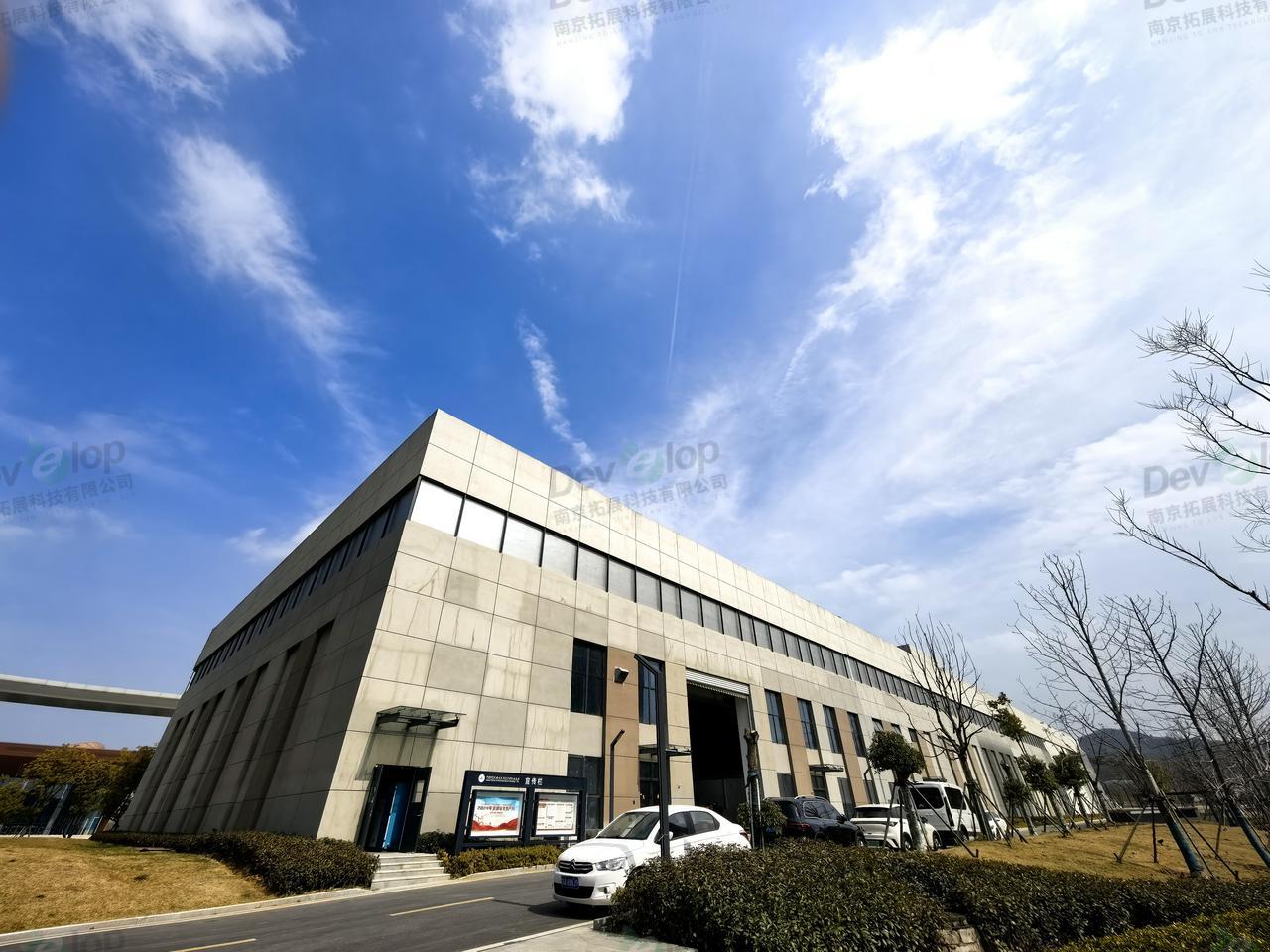
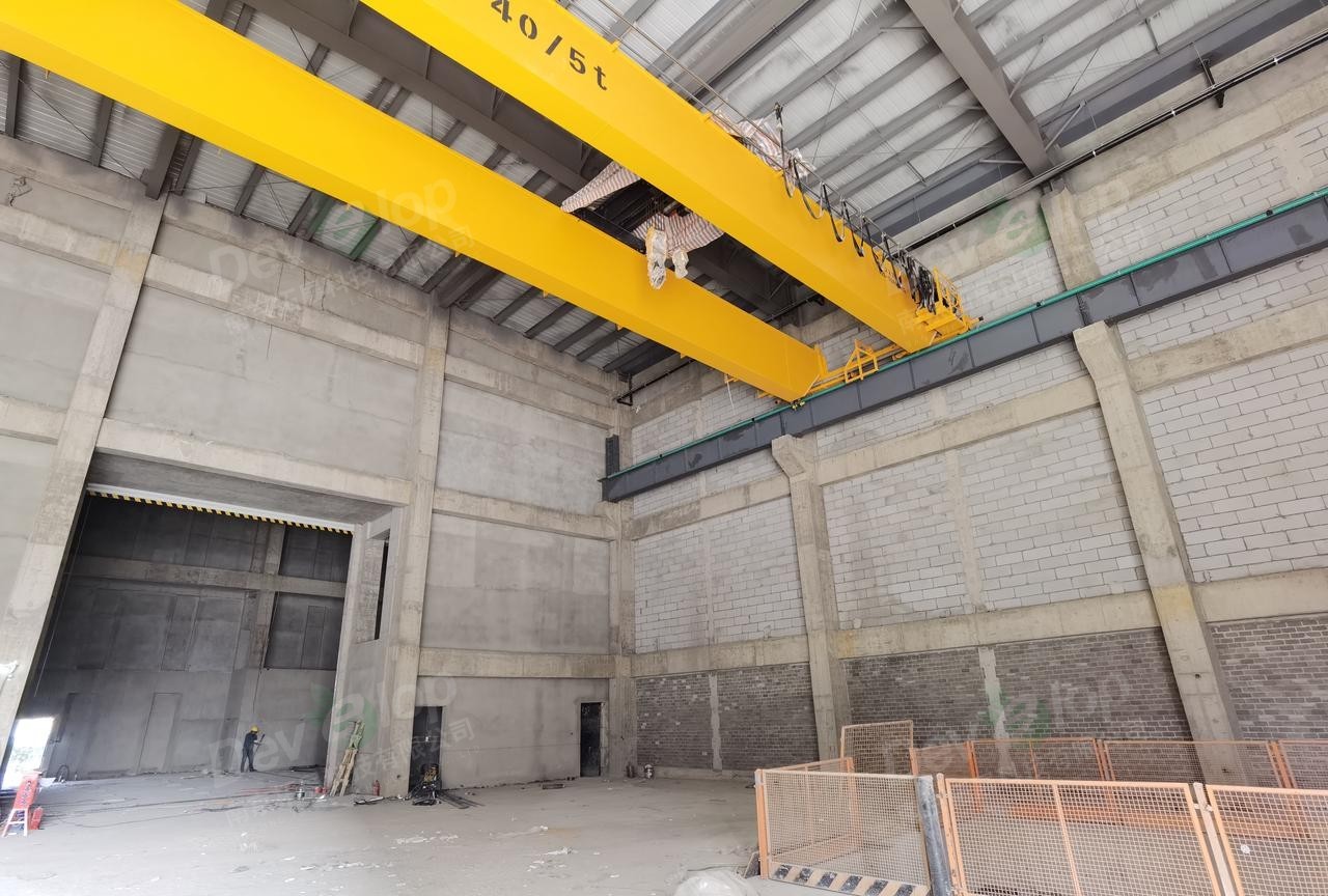
△ On-site photos
02 Construction Challenges and Solutions
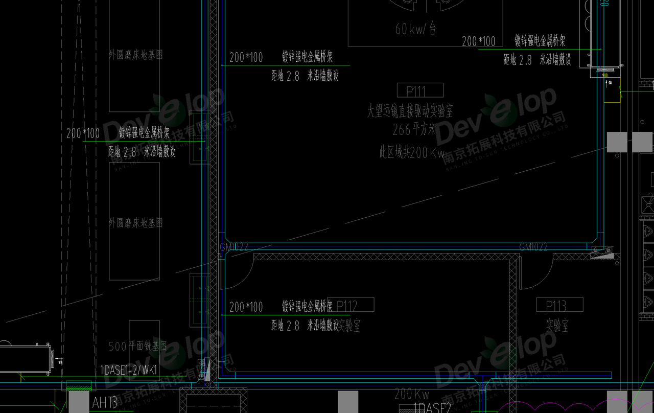
1、Civil engineering load-bearing challenges: Decentralized pipeline layout to mitigate risks
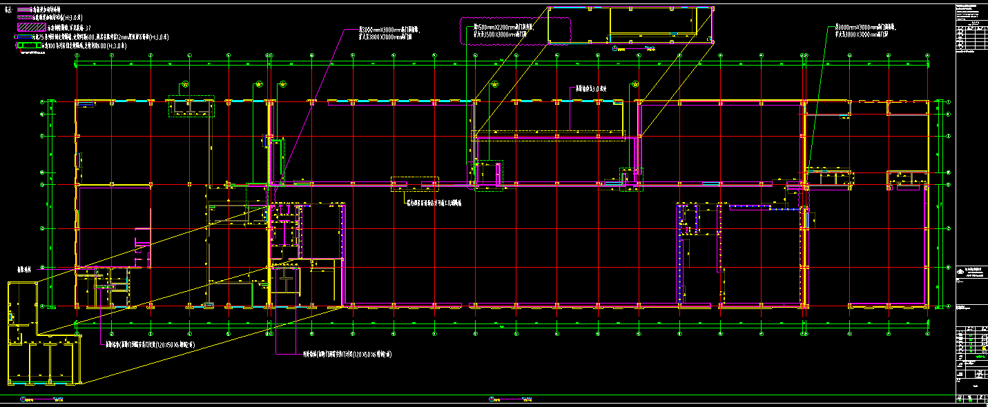
At the beginning of the construction, the insufficient load-bearing capacity of the original civil engineering building became the primary challenge. After joint verification of the weight of the top equipment by the electrical, HVAC, water supply and drainage, and fire protection disciplines and communication with the project manager, we adopted the strategy of "decentralized and concentrated regional pipeline installation positioning".The weight of the pipelines and equipment is evenly distributed to avoid local overload.This meets structural safety requirements and lays the foundation for subsequent construction.
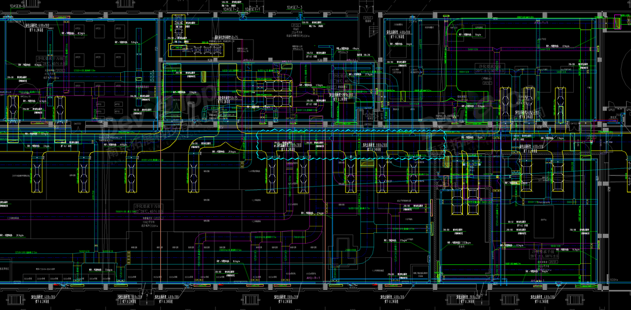
△ Combined plan of various disciplines, accurately dividing the load-bearing of key areas

△ Cross-sectional diagram of pipeline layout in key areas
2、"Space Scramble" between distribution boxes and HVAC vents
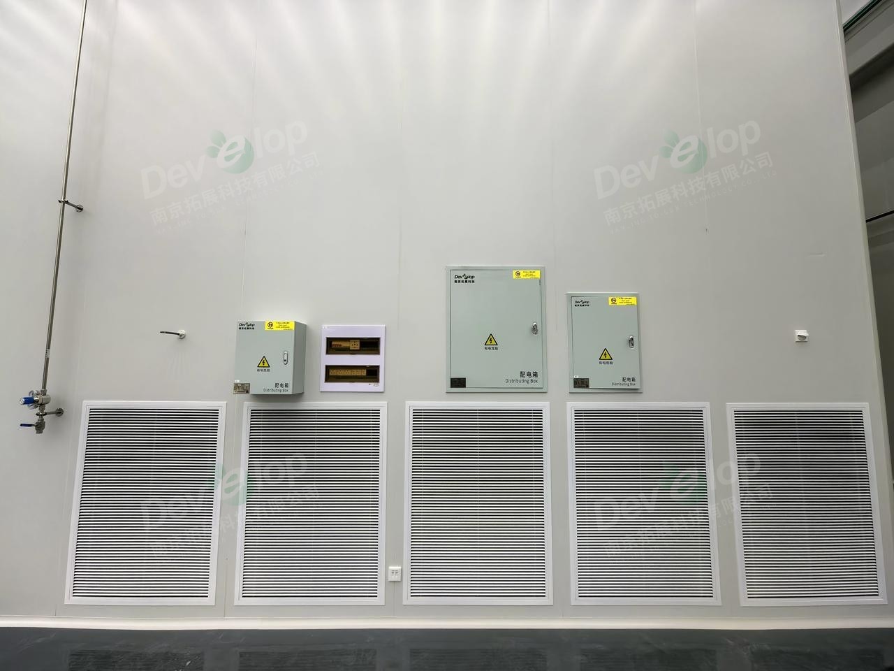
During the middle stage of construction, the installation of main distribution boxes and large equipment switch boxes frequently conflicted with the HVAC supply and return air vents. Through multiple interdisciplinary coordination meetings, we dynamically adjusted the equipment positions.Using methods such as "staggered installation" and "local avoidance" While ensuring the installation of distribution boxes, space is reserved for the HVAC system, ultimately achieving efficient space utilization.
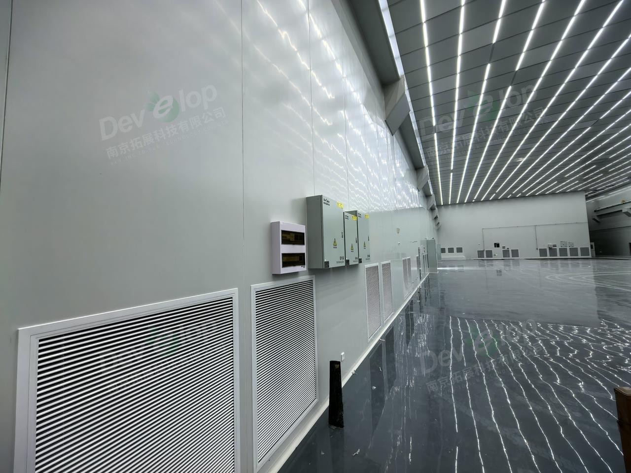
△ On-site photos (taken in February 2025): Staggered installation of distribution boxes and vents
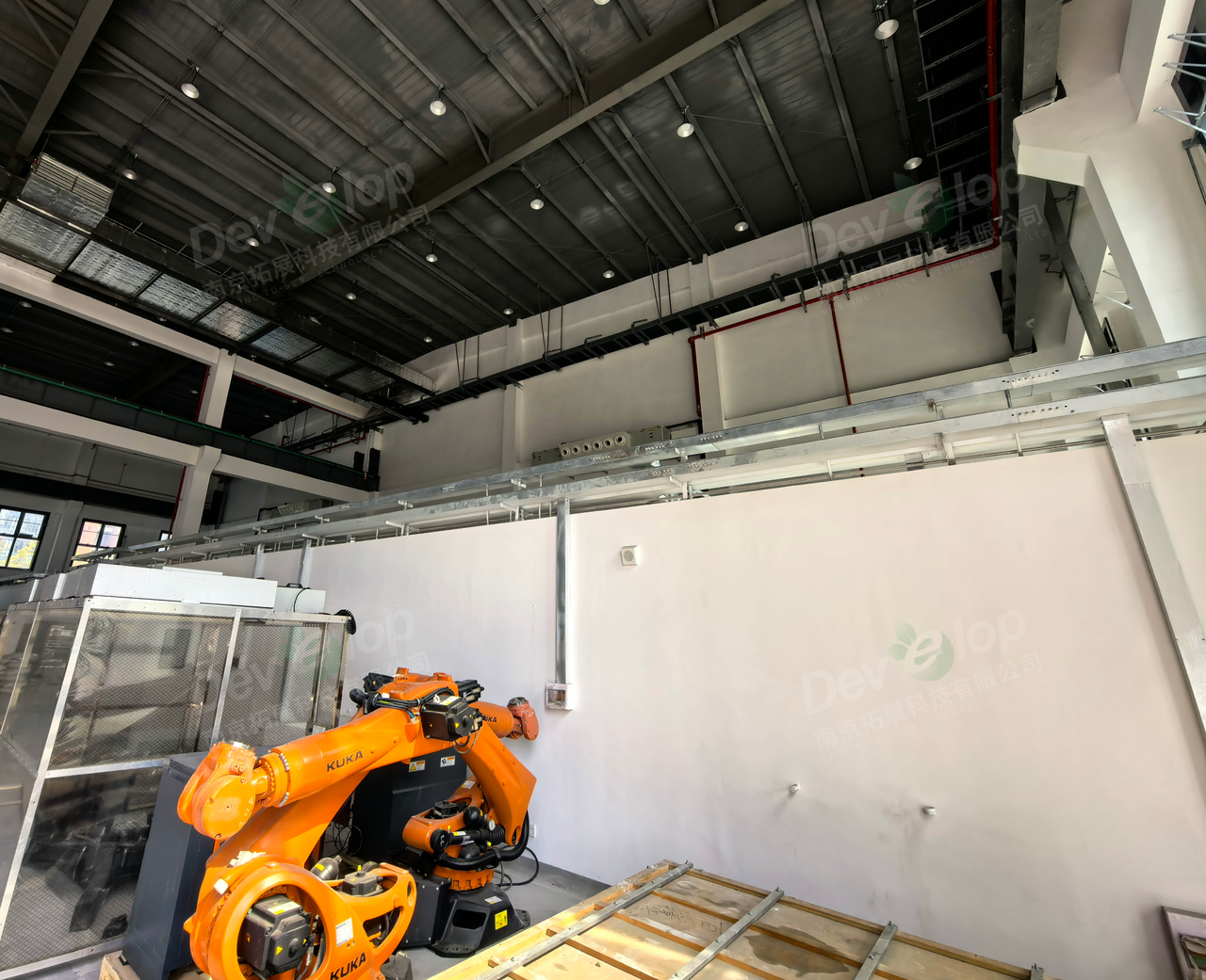
△ On-site photos (taken in February 2025): In areas where avoidance is impossible, the installation height of the distribution box is raised. The airflow organization within the color steel plate can also help cool the distribution box body.
3、Optimization of cable tray installation: Transformation from planar to three-dimensional design
The strong and weak current cable trays originally designed to be arranged along the wall were adjusted to a vertical installation method during construction due to load-bearing and aesthetic considerations. This change not only solved the problem of cable tray load-bearing hidden dangers but also improved the space neatness through three-dimensional layout, providing a new idea for similar cable tray designs.
△ Original design drawings, cable trays laid along the wall
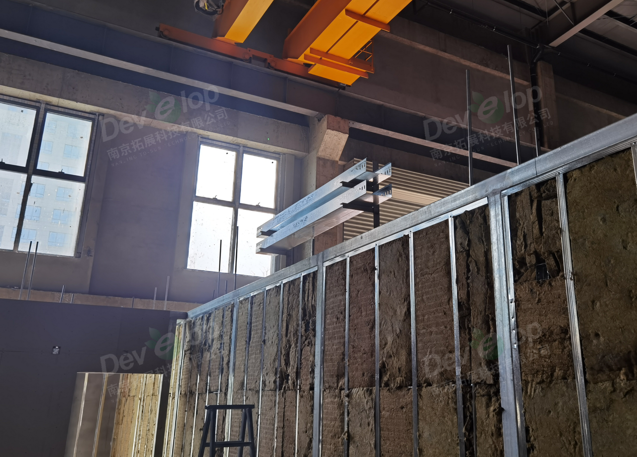
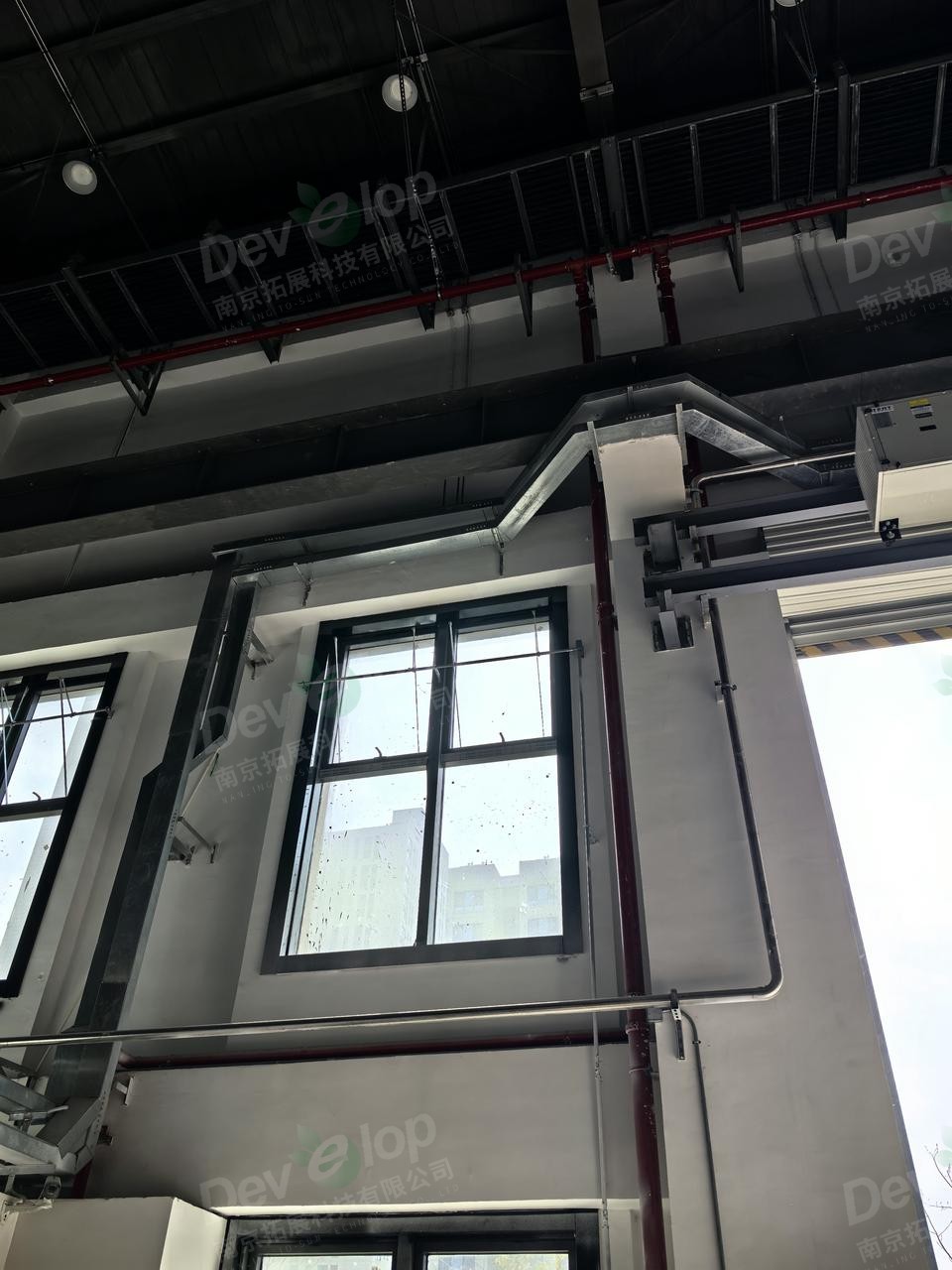
△ On-site photos (taken in March 2024): Top-mounted cable tray
△ On-site photos (taken in February 2025): Final effect of top-mounted cable trays
03 Completion Results and Design Implementation Presentation
After completion, we revisited the site, and the design concept has been transformed into a real scene:
1、Before and after construction comparison
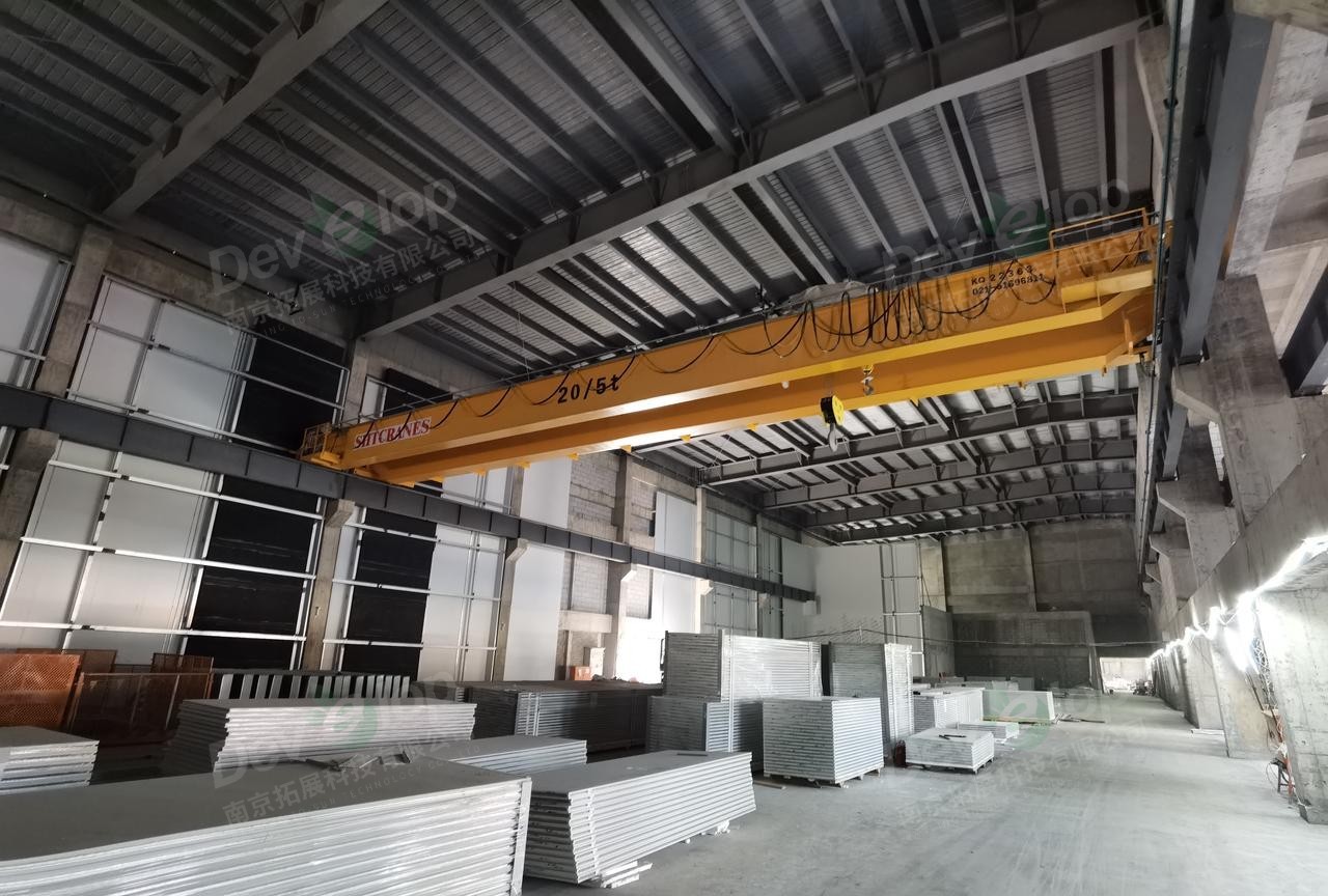
△ On-site photos (taken in March 2024): 1992 square meter fine grinding and polishing area laboratory during construction
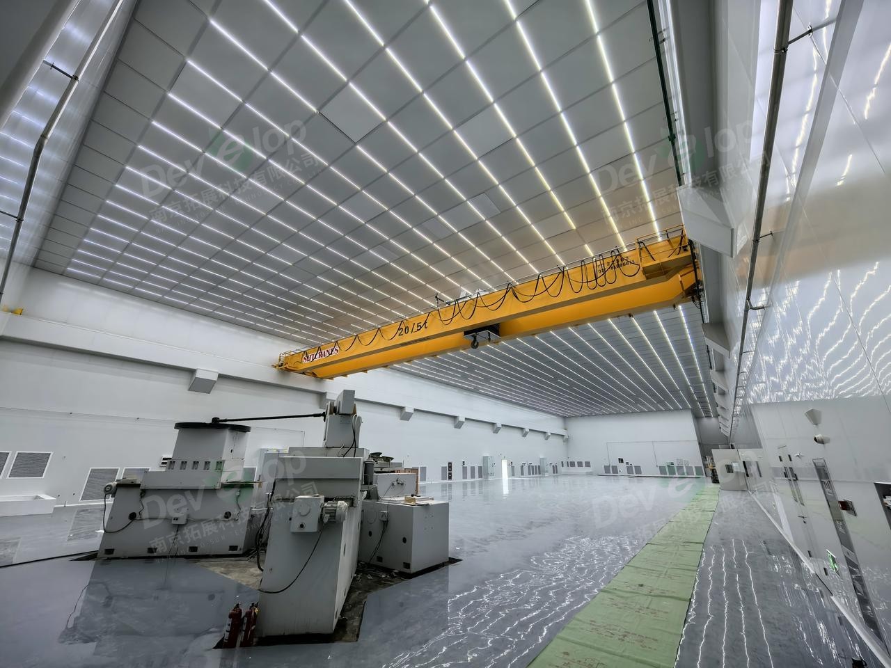
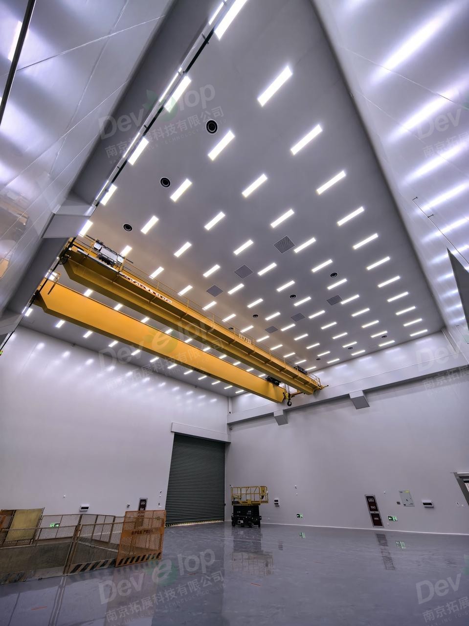
△ On-site photos (taken in February 2025): 1992 square meter fine grinding and polishing area laboratory after completion, the same position, the top is composed of full FFUs, and the lamps are LED T-shaped keel lamps.
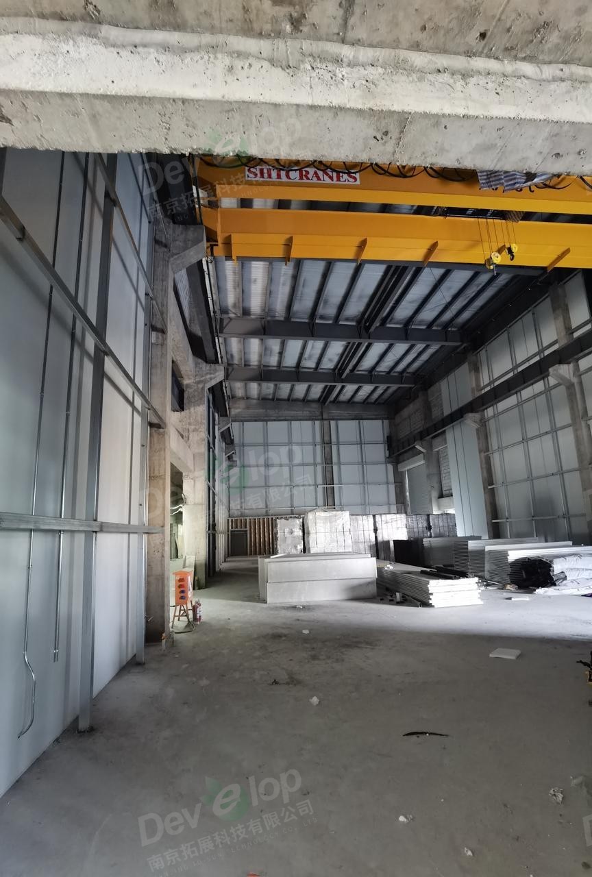
△ On-site photos (taken in March 2024): 435 square meter large-diameter ring polishing laboratory during construction
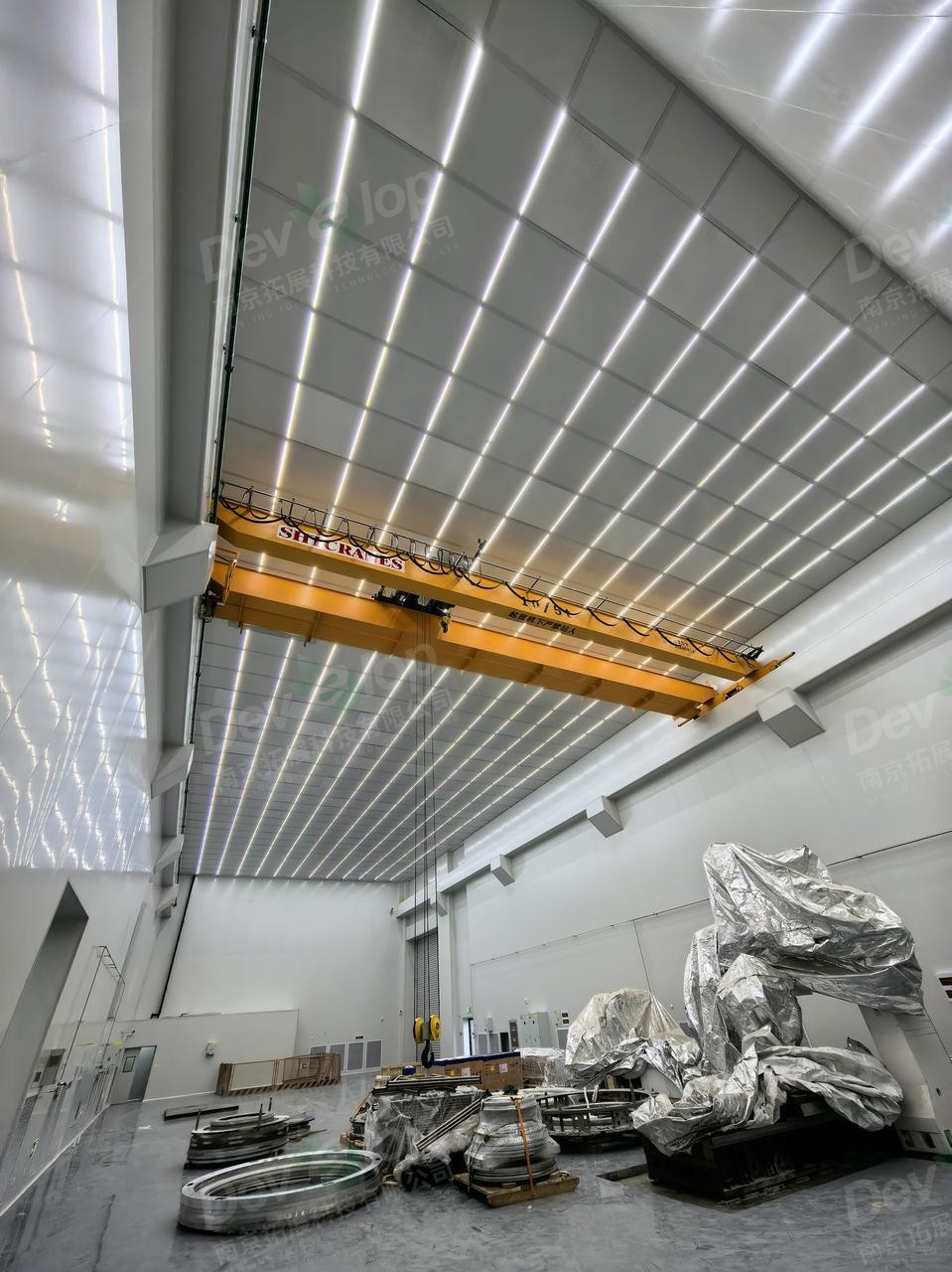
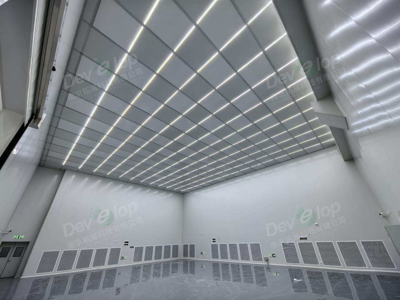
△ On-site photos (taken in February 2025): 435 square meter large-diameter ring polishing laboratory, the top is composed of full FFUs, and the lamps are LED T-shaped keel lamps.
△ On-site photos (taken in March 2024): 745 square meter assembly, vertical testing area laboratory during construction
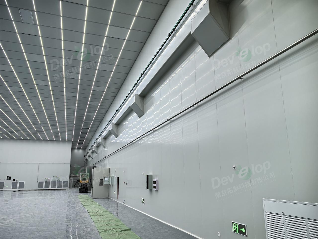
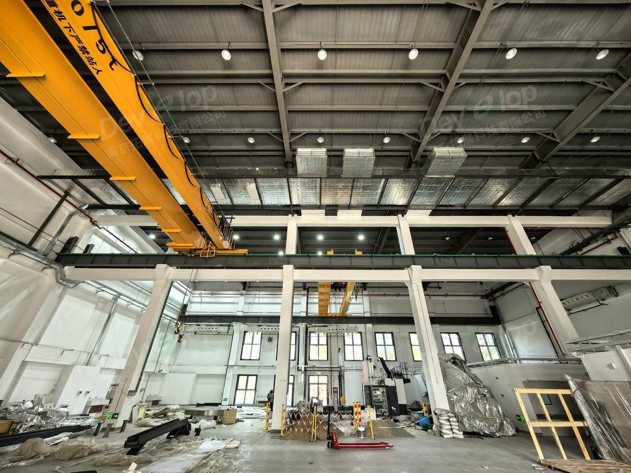
△ On-site photos (taken in February 2025): 745 square meter assembly, vertical testing area laboratory, the top material is color steel plate, and the lamps are ceiling-mounted LED clean lamps.
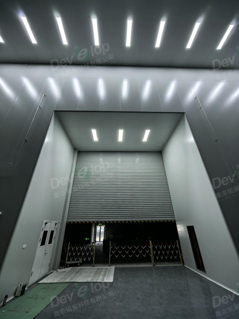
△ On-site photos (taken in February 2025): 745 square meter assembly, vertical testing area laboratory transition area door edge, lamps are also installed to supplement illuminance.
△ On-site photos (taken in February 2025): 489 square meter Wuhan laboratory, precise positioning of distribution boxes and HVAC vents, making the space flow clear and orderly.
2、Partial details
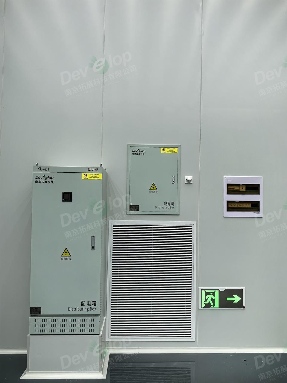
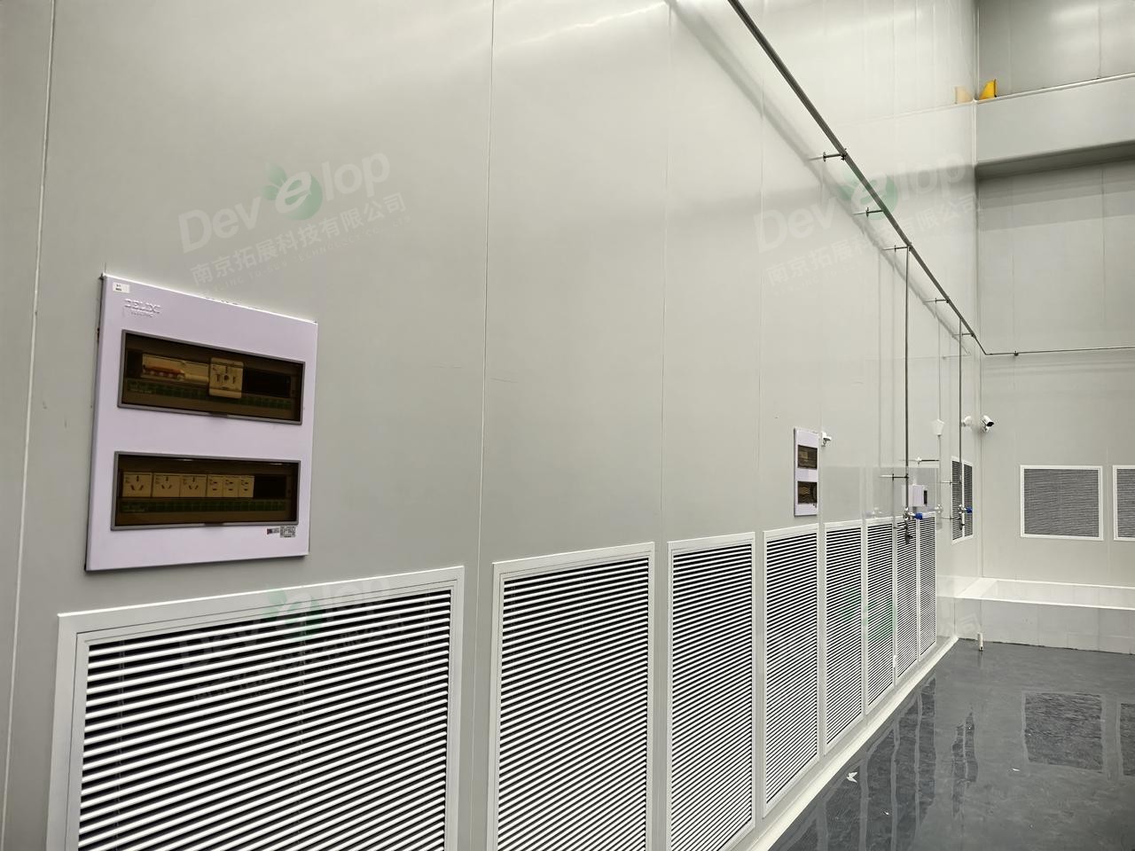
△ Equipment installation is staggered and orderly, from left to right: equipment main distribution box, vent, equipment distribution switch box, emergency escape sign, and socket box.
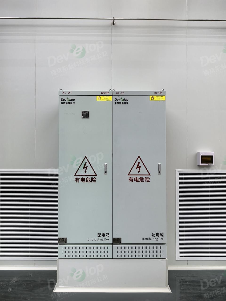
△ The strong current box is beautifully installed.
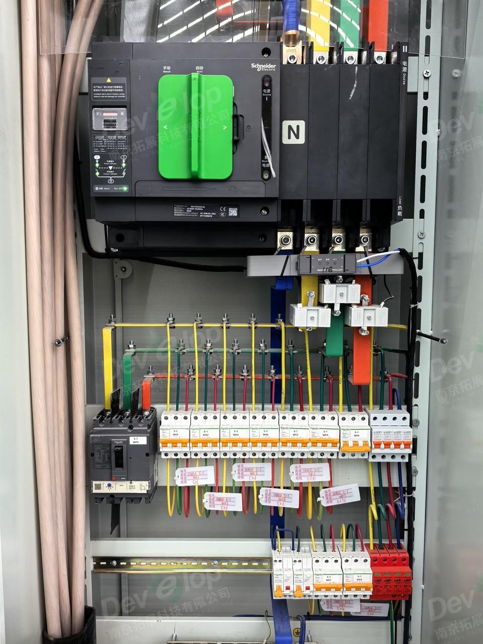
△ Circuit numbering in the distribution box is clear.
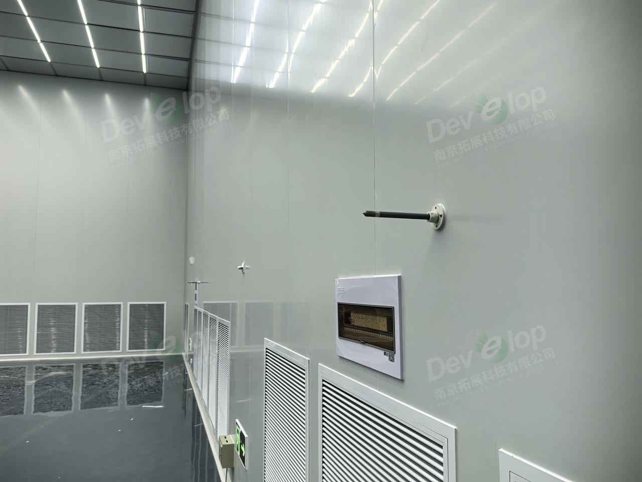
△ Equipment installation is staggered and orderly, from bottom to top: equipotential terminal box, emergency escape sign, vent, socket box, and temperature and humidity sensing probe.
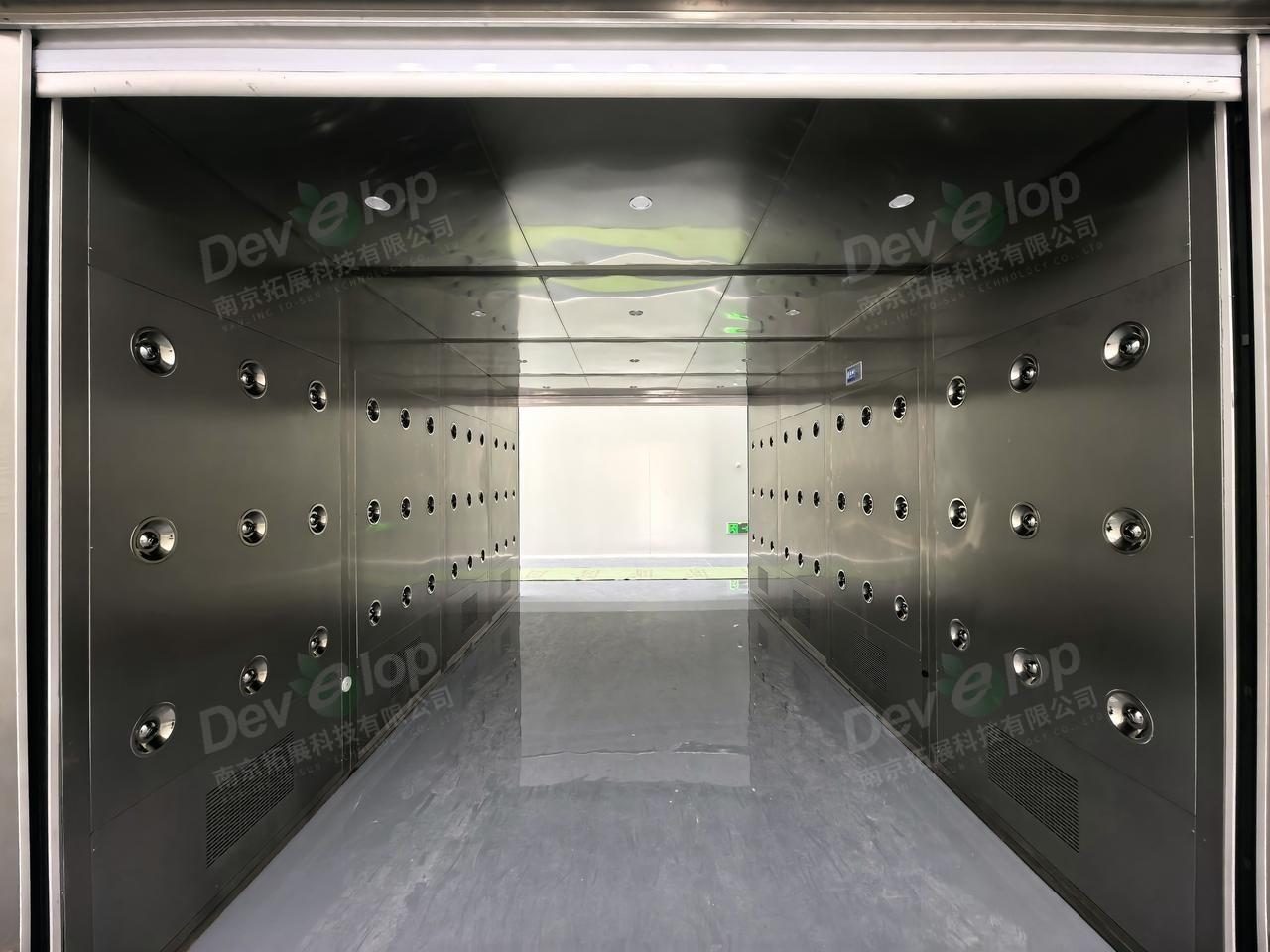
△ Air shower room
△ Equipment installation is staggered and orderly, from left to right: socket box, vent, socket box, gas pipeline, and gas points.
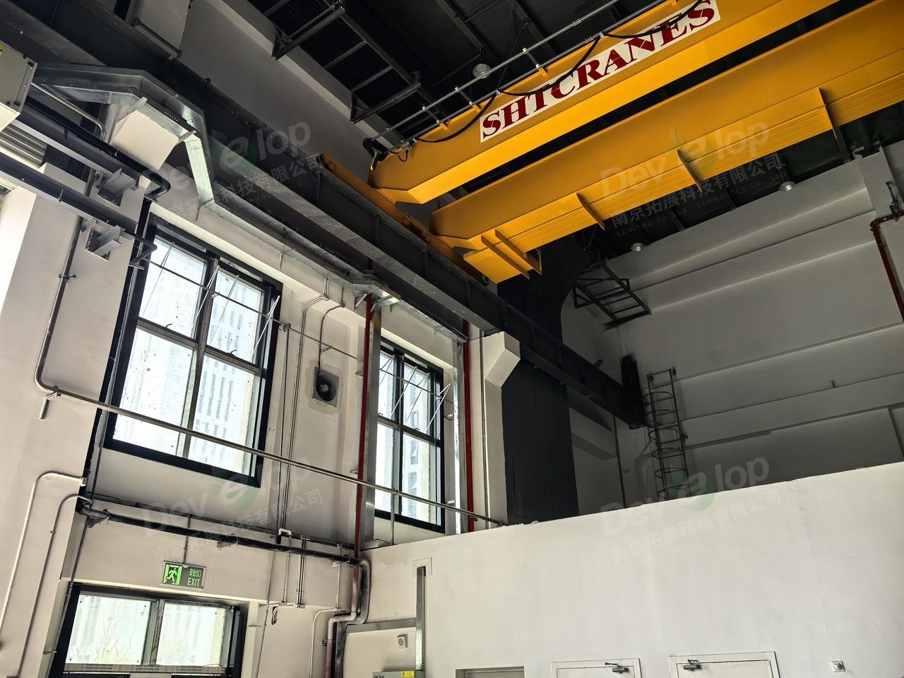
△ The top gantry support track is wrapped with color steel plate to ensure the cleanliness requirements in the large space.
△ Detailed surface-mounted cable tray and pipeline installation
△ Detailed surface-mounted cable tray and pipeline installation
△ Rough grinding area, no cleanliness requirements
Related News

Committed to becoming a leader in the field of laboratory construction in China

WeChat Public Number
Nanjing To-Sun Technology Co.,Ltd
sale@to-sun.com
Address: 6th Floor, Anke Building, 31 Guangju Road, jianye district, Nanjing